How to switch form line voltage thermostat to low voltage
- Thread starter JPride
- Start date

I was planning on the Amazon stat. I do not really need a smart stat for my system. Just looking for something programmable that I can control over Wi-Fi to keep the pets warm during cold snaps. I was also thinking to just settle for another 120v stat if this proves to difficult or expensive.
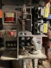
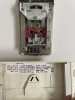
attached are images of stat and relay.
Thanks, AC
attached are images of stat and relay.
Thanks, AC
Attachments
-
 189.4 KB Views: 75
 -
 177.7 KB Views: 82
Looks like the system is set up as follows:
Load goes into a junction box
Out of that junction box
1 line to goes to emergency shut off switch
1 line to thermostat
1 line to the Aquastat
Out of the Aquastat
1 line to circulator pump
1 line to a relay box
Out of the relay box
1 line to the burner
Load goes into a junction box
Out of that junction box
1 line to goes to emergency shut off switch
1 line to thermostat
1 line to the Aquastat
Out of the Aquastat
1 line to circulator pump
1 line to a relay box
Out of the relay box
1 line to the burner
- Joined
- May 15, 2021
- Messages
- 397
- Reaction score
- 47
- Country

Ok, the pictures where of significant help. Your tracing the location/ID of the conductors was good too. Thank-You!
Unfortunately, for that thermostat, as you mentioned in your original post, you would in fact need a transformer and relay in/at your furnace location. I looked at NEST and Ecobee as well.....no go neither.
If you want, I can draw it out for you.....or, of course, you can go get another line voltage thermostat and be done with it.
- Joined
- May 15, 2021
- Messages
- 397
- Reaction score
- 47
- Country
I am drawing this up. I need one bit for information before I can draft this.
REASON: Some heating valves are "fail safe", that is, they fail open. So, in the case of a wiring failure (cable going to the valve is damaged), the valve fails OPEN, thus in heating as water is circulating through it's respective radiator.
I need to know if your heating system starts when the switchleg of the thermostat is energized OR de-energized?
You will need an extension cord for this. Please measure your two (2) wires for 120v-to-ground. Measure to ground in the extension cord, NOT the other conductor in the thermostat. The ground (in the extension cord) is the center lower U-shaped female port at the female end of the extension cord. You don't have a ground at the thermostat....hence, you've the extension cord so as to have a ground reference.
Tell me what happens to BOTH conductors when it's:
- Not heating....Is the black live? Is the white live? Both live?
- When heating...Is the black live? Is the white live? Both live?
You should use a meter for this, not an inductive no-contact "TICK" tester ("Google" it). REASON: "TICK" testers operate on the presence of induction, and they can produce horrible false-positives for results. I can use them, but a homeowner can get VERY confused by them for this application.
Thank you the comprehensive approach to this. Right now I can say that the system starts when contact is being made at the thermostat. When I turn up the temp the metal outer plate in the stat closes to make contact and turns everything on. Not sure this is of any help. I will have to further test to see when and which lines are being powered.
- Joined
- May 15, 2021
- Messages
- 397
- Reaction score
- 47
- Country
Ok, you'll see I've drawn the wiring needed for a new t-stat (Amazon is fine, but it's regardless).
The drawing is fundamental / concept only.
You would need AT LEAST three conductors, but 5 conductor is standard procedure, that is, #18 AWG - 5-wires/conductors. (Your US Home Depot Cat # = Model# 210-1005BR )
You'll need a 120-to-24 vac transformer, 40mA minimum (Home Depot = Model #AT72D, Store SKU = 977267)
You'll need a 24vac relay c/w at least one set of C, NO, NC contacts (form C). (Model LY2 - AC24 at an electrical wholesalers).
You'll need your new t-stat of course.
Ask a Question
Want to reply to this thread or ask your own question?
You'll need to choose a username for the site, which only take a couple of moments. After that, you can post your question and our members will help you out.
Similar Threads
Forum statistics
Latest Threads
-
Repairing fresh skim of moldy rough cement window sill.
- Started by medusa1569
-
Discontinued Flooring Needed
- Started by xDEEE
-
Thassos island in Greece with Tenere700 and swimming in a Cave.
- Started by mallllias
-
back deck roof question
- Started by helixman
-
Acrylic sink
- Started by Marty
-
Should a text detector influence trust in a DIY project write-up?
- Started by ethanjamescolez
-
Help with fallen down blind from ceiling
- Started by Helpwithdiynh
-
Jacuzzi shower set Lyndsay 0553445
- Started by MarineBob
-
What are the Types of Laminates?
- Started by anahitakhatri