Help interpret electrical diagram for hob

Joined
Aug 15, 2022
Messages
3
Reaction score
0
Hello
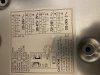
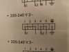
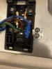
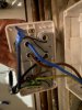
I am trying to wire a new hob. In the attached diagram L1 goes in connection point 1 which is linked to connection points 2 and 3 (I used copper horseshoes provided). What does the line coming out of connection point 3 mean? Ditto connection point 5?

Thanks
 

Attachments

Joined
May 15, 2021
Messages
397
Reaction score
47
Country
Canada
It's a drafting/drawing idiosyncrasy. Forget/ignore the small "go-nowhere" tails from terminals 3 and 5. Electrically speaking, they are identical to the voltage potential you'll have on L1 and L2. The manufacturer was also identifying this as 2~ (or 2 phase?)....this too is incorrect...there's no such thing as 2Ø.
 
Joined
Aug 15, 2022
Messages
3
Reaction score
0
Thank you AC Power. I thought this replacement would be simple but the manufacturer moved to 4 core cable and didn’t use the neutral so I’m on unfamiliar ground! At the two gang switch end, at the moment the L1 and L2 wires are connected together. Is that correct or should they be connecting to different locations?
 
Joined
May 15, 2021
Messages
397
Reaction score
47
Country
Canada
The L1 and L2 in your first-most picture (the wiring diagram) should not be connected together anywhere....that's a dead short!

However, in your two gang switch (picture 1984B...), the L1 will switch to L2, and N1 will switch to N2. So, when you energize this, you should read 240vac (or 220, whatever voltage your country is using) from L1 to N1. With the switch in the OFF position, you should read zero volts across L2 and N2. With the switch in the ON position, you should now read 240vac across L2 and N2.
 

Ask a Question

Want to reply to this thread or ask your own question?

You'll need to choose a username for the site, which only take a couple of moments. After that, you can post your question and our members will help you out.

Ask a Question

Top