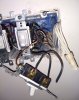
First, you do not need a Master Electrician to resolve this. A Licensed Journeyman. The key is the word "Licensed". The picture you attached doesn't help me because I cannot see what is wired to what.
In terms of Switches 101, Snap switches do not use "Neutral", the white wire. Some specialty switches do require a Neutral connection but the picture does not show specialty switches. They are simple "snap" switches.
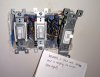
Beginning at the right of your picture, Switch #1, are there black wires connected to each of the screws on the side of the switch? Or is the top wire "White" and the bottom wire "Black" or vice-versa? Your picture shows the wrong side of the switch.
Center switch #2 and left switch #3, are they three-way switches. Are they part of circuits that turn lights on from two different places? I ask this because I see a "Red" wire in the box which usually means there are "Runners" which are used by three way switches.
Now to the diagnostics, did this switch ever work properly and then it's purpose was changed to do the scones?
There are two ways to bring power to a switch. One is the direct method, usually a simple tap off the back of a receptacle directly to the switch. Black from the receptacle is connected to the top screw on the switch. A cable from the overhead light is run and the black wire at the switch is connected to the bottom screw of the switch.
The Neutrals (White from both cables are connected together at the switch outlet. The cable from the switch to the light is connect at the light by connecting Black to the light and Neutral from the cable to Neutral from the light. Simple, easy-peasy.
The other way is not so simple. It's called a switch loop. Power is brought to the overhead outlet box. A cable is then fed to the switch outlet box. Here is where most folks get really uneasy, but trust me is the proper procedure to follow.
The white wire that is going to the switch is connected to the black power feed to the outlet. Take a piece of black electrical tape and wrap it around the white conductor. That's called re-tasking and it is allowed by code.
At the other end of the cable, wrap black tape around the white conductor from the feed (power) and connect it to the top screw on the switch. The black wire now get connected to the bottom screw.
Back at the fixture outlet, the black wire from the switch is connect to the black wire on the light and the white from the light is connected to the Neutral (white) coming from the supply line.
Unfortunatley, an awful lot of electrician, licensed or not, do not wrap tape around the Neutral wire going to the switch even though it is required by code.
Along comes a stranger and they see a white wire connected to a black, so they move it to the neutral connection and then you get breakers.
 176.4 KB Views: 263