- Joined
- Dec 14, 2012
- Messages
- 11
- Reaction score
- 0
Hi guys, I appreciate this is a common theme but I have searched and am just growing more and more confused.
I have a Worcester Greenstar 35CDi Combi boiler and am trying to replace a mechanical type honywell thermostat with a Seimens RDJ10RF/SET wireless thermostat.
Problem I have is the cables to the stat are very confusing.
Three cores
Blue
Brown
Yellow and Green
Simple I hear you cry.....
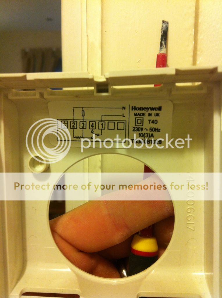
However looking in the manual for the boiler the three cables to the stat are marked up as
Lr
Ls
Ns
So which is which....?
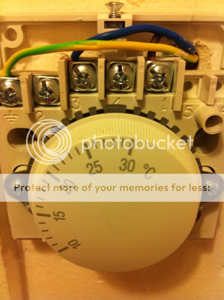
Looking at the old Honeywell stat (pictured below)

Again it looks very simple.
However it contradicts the boiler schematic which says there is no earth.
Also
When I put a meter on them I get strange results.
Honeywell stat wound to off position -
yellow/green to brown = 240v
yellow/green to blue = 100v
I'm assuming the 100v is nothing to worry about, but when I test the earth against another earth (on a nearby light switch) I read 170v
Really quite confused.
When the honeywell switches it opens brown to blue and sends 240v back through the blue cable.
I'm guessing I've not got any neutral in the thermostat.
Are there any wireless thermostats that require no neutral to power the reciever as my current mechanical stat is in a poor poistion and the house bakes before the stat gets warm enough to switch off.....
Any wise advice please!???
I have a Worcester Greenstar 35CDi Combi boiler and am trying to replace a mechanical type honywell thermostat with a Seimens RDJ10RF/SET wireless thermostat.
Problem I have is the cables to the stat are very confusing.
Three cores
Blue
Brown
Yellow and Green
Simple I hear you cry.....
However looking in the manual for the boiler the three cables to the stat are marked up as
Lr
Ls
Ns
So which is which....?
Looking at the old Honeywell stat (pictured below)
Again it looks very simple.
However it contradicts the boiler schematic which says there is no earth.
Also
When I put a meter on them I get strange results.
Honeywell stat wound to off position -
yellow/green to brown = 240v
yellow/green to blue = 100v
I'm assuming the 100v is nothing to worry about, but when I test the earth against another earth (on a nearby light switch) I read 170v
Really quite confused.
When the honeywell switches it opens brown to blue and sends 240v back through the blue cable.
I'm guessing I've not got any neutral in the thermostat.
Are there any wireless thermostats that require no neutral to power the reciever as my current mechanical stat is in a poor poistion and the house bakes before the stat gets warm enough to switch off.....
Any wise advice please!???