Hello! This is my first post. I did a jumpy note with my classmate. Now I want to post here.
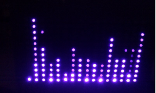
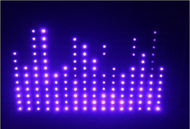
Firstly, here are the finished images :

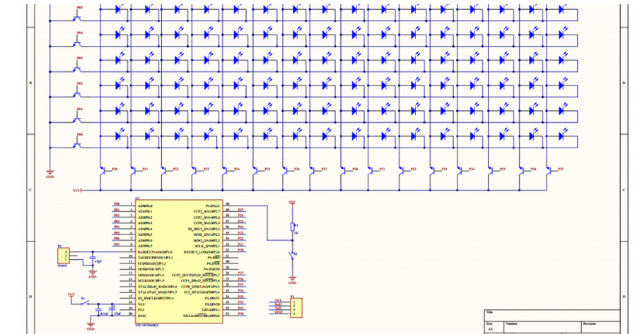
This is a circuit diagram. principle is very clear, but this screenshot is not very clear. LOL. We were going to do 16 x 8, and later we only bought 200 LEDs. So we decided to make 16 x 12, and we didn't draw the schematic again.
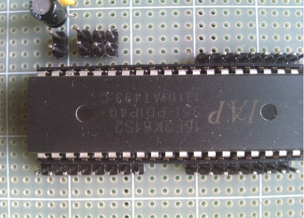
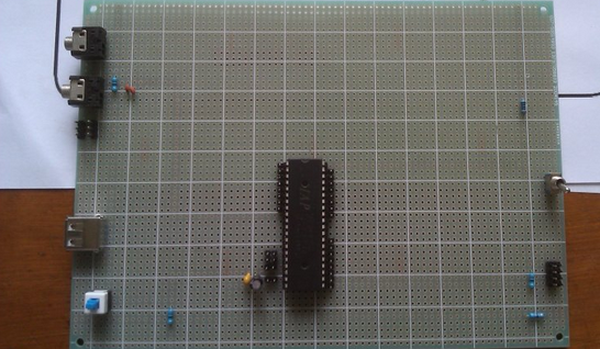
At first, we welding control panel. LED and transistor were bought on kynix semiconductor, and we were using a microcontroller IAP15F2K61S2. We bought it just for fun and now it make a difference. This chip was fast and very convenient, no external oscillator and reset circuit, comes with 10 ADC, 38 IO ports.
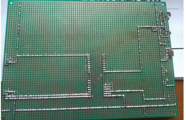
The welding of control panel was done mainly by my classmate. I weld a few lines, and to be honest my classmates welding better than me. I remember last time because we do not know that most Collage universal plate is attached to the power supply then caused short-circuit. This time just directly use two lines of up and down as Vcc, about two lines of left and right used as Gnd. In this way the project was easier.
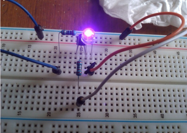
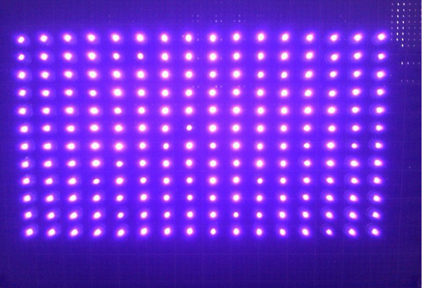
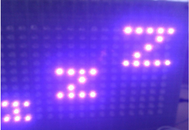
We tangled for a moment when selected LED color. Because we do not know if the effect of multicolor is good, then we decided to buy the blue. But we finally decided to buy purple.
Purple is indeed very domineering but brightness is a little dim. With a 10 ohm resistor to drive current limiting then brightness is like this. And the measured voltage drop over the 3.3V. Fine, let's do it ! Put them up. It seems quite spectacular. LOL.
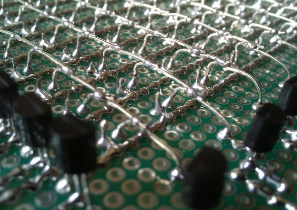
When torch the lights, he table may be uneven or did not put away, each of which needs to be adjusted. But fortunately I have solder a foot before, then adjusting one by one was very quickly. After weld a negative electrode lead out in sideways and the positive bristling hand in hand. This spend me a great deal of time. And fortunately no bad welding. Last time it burned out a few when welding light cube and it's very complicated to change them. This time we are very lucky.
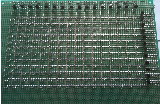
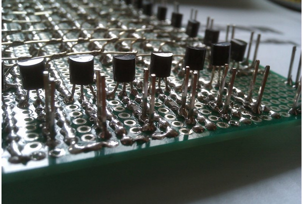
That comes with transistors and resistors. triode using a line of 8050 were bought from kynix semiconductor :http://www.kynix.com/. Resistor 0805, the current limiting resistor 10 ohms, the base resistance 10K. Finally, pin, we discovered that pin is the most difficult to weld.
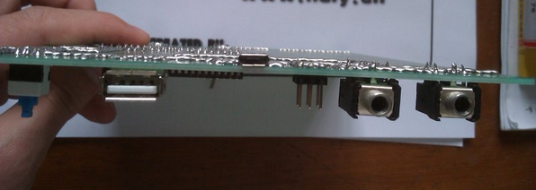
maybe I don't know how to weld this thing. It burnt me out to death! Here is the finished panel.
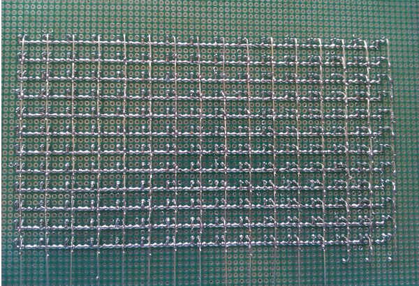
Here are some detail images. It seems that I have under estimate the 192 lights. I have dim eyesight.
Wow !
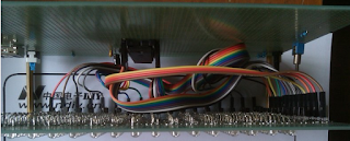
Two boards stacked up in the middle with Dupont line, the work is finished.
Due to limited capacity, coupled with time constraints, the effect is like that of the present. You
can have a try to find more interesting features.
There are a few questions to ask you:
This stuff will have a display even without sound signal.
if AD converter pin float it seems there will be a level change, or sometimes send up with a serial voltage, and how to do this?
Sound signal output from the computer sound card should be alternating current. generally a few hundred millivolts voltage to 1V, but I use AD converter is sent directly to the host computer is 0, I do not know what's wrong and I ignored it.
And automatic gain large volume does not matter, but the volume will not be identified if it
is too small.
The AD conversion accuracy may be the reason.
when boot animation zzz displayed noise are always there.
What's the problem? And how to solve it?
Firstly, here are the finished images :
This is a circuit diagram. principle is very clear, but this screenshot is not very clear. LOL. We were going to do 16 x 8, and later we only bought 200 LEDs. So we decided to make 16 x 12, and we didn't draw the schematic again.
At first, we welding control panel. LED and transistor were bought on kynix semiconductor, and we were using a microcontroller IAP15F2K61S2. We bought it just for fun and now it make a difference. This chip was fast and very convenient, no external oscillator and reset circuit, comes with 10 ADC, 38 IO ports.
The welding of control panel was done mainly by my classmate. I weld a few lines, and to be honest my classmates welding better than me. I remember last time because we do not know that most Collage universal plate is attached to the power supply then caused short-circuit. This time just directly use two lines of up and down as Vcc, about two lines of left and right used as Gnd. In this way the project was easier.
We tangled for a moment when selected LED color. Because we do not know if the effect of multicolor is good, then we decided to buy the blue. But we finally decided to buy purple.
Purple is indeed very domineering but brightness is a little dim. With a 10 ohm resistor to drive current limiting then brightness is like this. And the measured voltage drop over the 3.3V. Fine, let's do it ! Put them up. It seems quite spectacular. LOL.
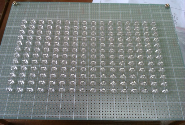
When torch the lights, he table may be uneven or did not put away, each of which needs to be adjusted. But fortunately I have solder a foot before, then adjusting one by one was very quickly. After weld a negative electrode lead out in sideways and the positive bristling hand in hand. This spend me a great deal of time. And fortunately no bad welding. Last time it burned out a few when welding light cube and it's very complicated to change them. This time we are very lucky.
That comes with transistors and resistors. triode using a line of 8050 were bought from kynix semiconductor :http://www.kynix.com/. Resistor 0805, the current limiting resistor 10 ohms, the base resistance 10K. Finally, pin, we discovered that pin is the most difficult to weld.
maybe I don't know how to weld this thing. It burnt me out to death! Here is the finished panel.
Here are some detail images. It seems that I have under estimate the 192 lights. I have dim eyesight.
Wow !
Two boards stacked up in the middle with Dupont line, the work is finished.
Due to limited capacity, coupled with time constraints, the effect is like that of the present. You
can have a try to find more interesting features.
There are a few questions to ask you:
This stuff will have a display even without sound signal.
if AD converter pin float it seems there will be a level change, or sometimes send up with a serial voltage, and how to do this?
Sound signal output from the computer sound card should be alternating current. generally a few hundred millivolts voltage to 1V, but I use AD converter is sent directly to the host computer is 0, I do not know what's wrong and I ignored it.
And automatic gain large volume does not matter, but the volume will not be identified if it
is too small.
The AD conversion accuracy may be the reason.
when boot animation zzz displayed noise are always there.
What's the problem? And how to solve it?
Last edited by a moderator: